The µEC3 is a 27 × 24 mm ESP32-C3 development board from µEDesign (Mu-ETronics, made in India) — a single-core 32-bit RISC-V running at 160 MHz with 4 MB flash, Wi-Fi 802.11 b/g/n, Bluetooth 5.0 LE, and a USB-C port wired directly to the chip’s own USB peripheral. No CP2102, no CH340, no USB-UART bridge in the signal path.
This is the complete working reference we use in the lab: the full specification table, an interactive pin explorer that shows every pad exactly where it sits on the board, power rules that will save you a dead LDO, the first upload in Arduino IDE, four sketches that compile as-is, and the seven mistakes that cost people an evening. Everything below has been checked against the board in hand and against Espressif’s own ESP32-C3 datasheet.
- SoC ESP32-C3-WROOM-02 (N4)
- Core RISC-V @ 160 MHz
- Flash 4 MB
- GPIO 14 usable
- USB Native USB-C
- Size 27 × 24 mm
What this guide covers
- Specifications — what is actually on the board
- Interactive pinout explorer (all 18 pads)
- Powering the board without killing the LDO
- First upload in Arduino IDE, with the right board settings
- Four working sketches — blink, Wi-Fi scan, ADC, deep sleep
- I²C, SPI, UART, PWM and where they land
- Seven things that trip people up
- Primary sources
Anyone soldering an ESP32-C3 board into a real project — a wearable, a battery sensor node, a BLE peripheral. If you are coming from an ESP8266 or an Arduino Uno, read the power and gotchas sections before you wire anything: the µEC3 is a 3.3 V board with a strapping pin on GPIO9, and 5 V on a GPIO will end the board.
A coin-sized ESP32-C3-WROOM-02 development board — 32-bit RISC-V at 160 MHz, 4 MB flash, Wi-Fi and Bluetooth LE, and native USB-C programming with no USB-UART bridge in the way. Built for low-power IoT sensing and wearables.
What is on the board
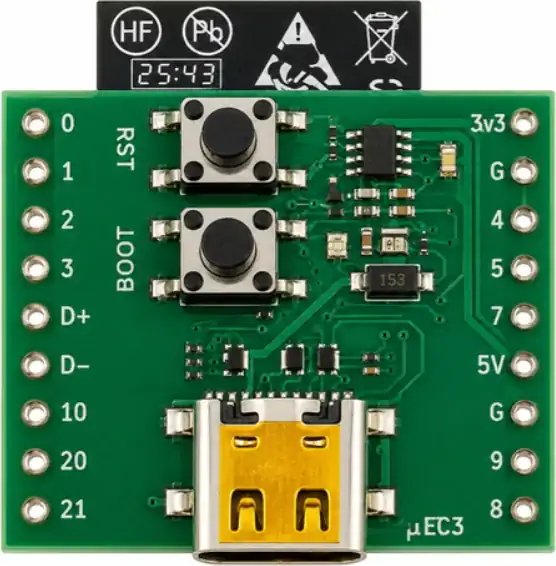
The µEC3 carries an ESP32-C3-WROOM-02 module (N4 variant, 4 MB flash) with a PCB trace antenna, an 800 mA LDO, RESET and BOOT buttons, a power LED, a user LED on GPIO6, and a USB-C port wired straight to the SoC’s own USB peripheral.
| Parameter | Value |
|---|---|
| Module | ESP32-C3-WROOM-02 (N4) |
| Board dimensions | 27 × 24 mm (2.7 × 2.4 cm) |
| Processor | 32-bit single-core RISC-V, max 160 MHz |
| ROM / SRAM | 384 KB ROM / 400 KB SRAM on-chip |
| Flash memory | 4 MB |
| Wireless | 2.4 GHz Wi-Fi (802.11 b/g/n), Bluetooth 5.0 Low Energy |
| Antenna | On-board PCB trace antenna |
| I/O pins | 14 GPIO with flexible function mapping, plus 5V input pin, 3V3 LDO output pin and 2 × GND |
| Interfaces | I²C, I²S, SPI, UART, PWM, TWAI (CAN), 12-bit ADC — 2 units / 5 inputs |
| On-board LEDs | User/status LED on GPIO6 · separate power indicator LED |
| Regulator | LDO, 800 mA capability, output exposed on the 3V3 pin |
| Programming | USB-C, native USB Serial/JTAG — no USB-UART bridge chip |
| Switches | On-board BOOT and RESET buttons |
| Toolchains | ESP-IDF, Arduino IDE, MicroPython / CircuitPython |
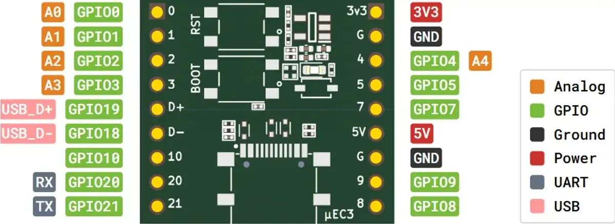
GPIO11–GPIO17 are tied up inside the module driving the SPI flash die, so they never reach the header. GPIO6 is on the board but wired to the user LED rather than to a pad. That leaves 14 usable GPIO on the two 9-pad rows.
Interactive pin explorer
Pads are laid out exactly as they sit on the board — nine on each side, silkscreen labels included. Pick a pad for its GPIO number, alternate functions, and the catches worth knowing before you solder something to it.
GPIO6 — user LED
Drives the on-board SMD
LED. Use it for status blinks; it is also the default FSPICLK / MTCK pin
if you remap SPI or JTAG.
GPIO11 – GPIO17
Reserved inside the module for the SPI flash interface. Never drive them.
GPIO matrix
I²C, I²S, SPI, UART, PWM and TWAI can be routed to almost any exposed GPIO. The “default” pins below are conventions, not hard wiring.
Powering the board
There are three ways in, and one of them can quietly destroy the module.
USB-C · 5 V
The normal path. VBUS feeds the LDO and reaches the 5V pad through a Schottky diode, so back-EMF from your circuit cannot push into the host port.
5V pad · 5 V in
Feed a regulated 5 V supply here when running off a battery pack or a carrier board. The on-board LDO drops it to 3.3 V for the module.
3V3 pad · output
The LDO output, rated 800 mA total. Use it to power sensors and peripherals — the module’s own draw comes out of that same budget.
3V3 is the regulator’s output, not a second input. Driving it from a 5 V rail back-feeds the LDO and puts 5 V across a 3.3 V module. Every GPIO on this board is 3.3 V logic — level-shift anything that talks at 5 V.
Wi-Fi transmit bursts pull a few hundred milliamps for a few milliseconds. If the board browns out or resets when the radio comes up, add a bulk capacitor (100 µF or more) across 3V3 and GND close to the module, and check that your 5 V source can supply the peak.
GPIO0–GPIO5 sit in the RTC domain, so they can wake the chip from deep sleep. That is the pin group to design your wake-on-event sensor around — the rest of the GPIO are powered down while sleeping.
First upload, Arduino IDE
Because programming goes through the SoC’s native USB Serial/JTAG peripheral, there is no CP2102 or CH340 driver to install. Plug it in and the port appears.
- Install the Arduino IDE.
Any recent 2.x release.
- Add the ESP32 board package URL.
File → Preferences → Additional boards manager URLs:
https://raw.githubusercontent.com/espressif/arduino-esp32/gh-pages/package_esp32_dev_index.json
- Install the esp32 core.
Tools → Board → Boards Manager, search
esp32, install the latest version. - Select the board.
Tools → Board → esp32 → ESP32C3 Dev Module.
- Turn on USB CDC On Boot.
Tools → USB CDC On Boot: Enabled. Without this the Serial Monitor stays silent — the vendor calls this out explicitly.
- Pick the port and upload.
Select the port that appears when the board is plugged in, then hit Upload.
On this board
Serial is the USB CDC device, not a UART. If that setting is
left disabled, your sketch still runs but nothing reaches the Serial Monitor. This is
the single most common “my board is dead” report — it usually isn’t.
Recommended board settings
| Setting | Value | Why |
|---|---|---|
| Board | ESP32C3 Dev Module | Matches the WROOM-02 module |
| USB CDC On Boot | Enabled | Routes Serial to native USB |
| Flash Size | 4MB (32Mb) | N4 module |
| CPU Frequency | 160 MHz | Drop to 80 MHz or 40 MHz to save power |
| Partition Scheme | Default 4MB with spiffs | Switch to “Huge APP” if the sketch overflows |
| Upload Speed | 921600 | Drop to 115200 if uploads fail |
Manual download mode
The IDE normally resets the board into the bootloader on its own. When it cannot — a sketch that crashes immediately, or a deep-sleep loop that never enumerates USB — do it by hand with the two buttons:
- Hold BOOT.
This pulls GPIO9 low.
- Tap RESET while still holding BOOT.
The chip samples GPIO9 at reset and enters the ROM serial bootloader.
- Release BOOT, then upload.
Press RESET once more afterwards to run your new sketch.
Working sketches
These are the four examples shipped in the µEDesign repository, verbatim, with their original comments. Each compiles against the esp32 Arduino core with the settings above.
The Wi-Fi manager sketch is long because it embeds two full HTML pages. Connect to the
access point ESP32C3-WiFiManager (password 12345678) and open
192.168.4.1 to scan and join a network from the browser.
Interfaces and where they land
The ESP32-C3’s GPIO matrix routes most peripherals to any pin you name in software. The pins listed here are the defaults the silicon and the Arduino core assume when you do not say otherwise.
ADC — 12-bit
Two converter units, five inputs on the header. analogRead() returns
0–4095. ADC2 shares hardware with the Wi-Fi radio, so its reading is unavailable while
Wi-Fi is running.
ADC2: GPIO5
UART
UART0 is the classic serial console. On this board Serial is USB CDC
instead — use Serial0 or Serial1 for a hardware port.
UART1: any free GPIO
I²C
One I²C controller, fully remappable. Call Wire.begin(sda, scl) with
the pins you actually wired. Add 4.7 kΩ pull-ups to 3V3 if your breakout has none.
SPI (FSPI / SPI2)
The user-accessible SPI controller. Defaults below; override them in
SPI.begin(sck, miso, mosi, ss).
MOSI: GPIO7 · CS0: GPIO10
PWM (LEDC)
Six independent channels, any GPIO, up to 14-bit resolution. Use
ledcAttach(pin, freq, bits) on core 3.x.
I²S & TWAI (CAN)
One I²S bus for audio codecs and MEMS microphones, and one TWAI controller for CAN — TWAI still needs an external transceiver.
USB Serial/JTAG
GPIO18 and GPIO19 are hard-wired to the USB-C port. They carry flashing, the Serial Monitor and hardware debugging all at once.
RTC / deep sleep
Only the low-numbered pins stay alive in deep sleep and can wake the chip on an external edge or level.
Things that trip people up
Serial Monitor prints nothing
setup() — USB CDC takes a moment to enumerate, so
the first few Serial.println() calls can vanish:
while (!Serial && millis() < 3000) delay(10);The port disappears after upload
while(1), or deep sleep stops the CDC device from enumerating and the port
vanishes. Hold BOOT, tap RESET, release BOOT to force the ROM bootloader, then upload
a known-good sketch.The board will not boot after I wired up my circuit
analogRead() on GPIO5 returns garbage when Wi-Fi is on
Can I use GPIO18 and GPIO19 as normal I/O?
Where is the built-in LED?
#define LED_PIN 6Sketch too large
Antenna placement
What it is built for
µEDesign targets the µEC3 at low-power sensing where physical size matters more than raw compute.
- Smart homes
- Industrial automation
- Health care devices
- Consumer electronics
- Smart agriculture
- Low-power IoT sensor hubs
- Low-power data loggers
- Wearables
Primary sources
Everything on this page traces back to these. When something here disagrees with a datasheet, the datasheet wins.
Frequently asked questions
Is the µEC3 the same as an ESP32 board?
No — and the difference matters. The classic ESP32 is a dual-core Xtensa LX6 at 240 MHz with Bluetooth Classic. The µEC3 carries an ESP32-C3: a single-core 32-bit RISC-V at 160 MHz, Bluetooth 5.0 LE only (no Bluetooth Classic, so no A2DP audio or classic serial profiles), and no built-in DAC or touch peripheral. In exchange you get lower power draw, native USB, and a much smaller board. For sensor nodes, wearables and BLE peripherals the C3 is usually the better choice; for audio, camera work or anything needing PSRAM and vector maths, use an ESP32-S3 instead.
Why can't I find GPIO11 to GPIO17 on the header?
They are physically inside the module, wired to the SPI flash die, and never reach a pad. GPIO6 exists on the board but drives the user LED. That leaves 14 GPIO on the two 9-pad rows. Trying to reassign the flash pins in software will hang the chip on the next boot.
Do I need to press BOOT to upload?
Normally no. Because the USB-C port is wired to the ESP32-C3's native USB Serial/JTAG peripheral, the chip resets itself into download mode when the toolchain asks it to. You only need the manual BOOT + RESET sequence when a sketch has crashed the USB stack, when deep sleep runs immediately on boot, or when you have reassigned GPIO18/GPIO19. The manual download mode steps are in the first upload section.
Can I power the µEC3 from a LiPo battery?
There is no charger or protection circuit on the board, so you cannot wire a single cell straight to a charge-and-run setup. A 3.7 V LiPo can feed the 3V3 pin only through a proper regulator or when the cell is within the module's 3.0–3.6 V window — feeding a fully charged 4.2 V cell into 3V3 exceeds the module's absolute maximum. The clean approach is a TP4056 charge board plus a 3.3 V buck/LDO into the 3V3 pin, with the on-board LDO left unused.
Which toolchains work with this board?
ESP-IDF (Espressif's native framework), the Arduino ESP32 core, and MicroPython or CircuitPython builds for the ESP32-C3. In Arduino IDE, select a generic ESP32C3 Dev Module and enable USB CDC On Boot so Serial maps to the native USB port — that one setting is the most common reason a beginner sees an empty Serial Monitor.
How much current can the 3V3 pin supply to my sensors?
The on-board LDO is rated at 800 mA, but that is the regulator's capability, not a budget you can spend freely. The module itself pulls up to ~350 mA in Wi-Fi transmit peaks, and the LDO's thermal limit on a 27 × 24 mm board with no heatsink arrives well before 800 mA. Budget roughly 200–300 mA for peripherals, and give anything with a motor, heater or radio its own supply with a common ground.
Build this on real hardware
eARgle Innovation Labs kits ship with the sensors, boards and wiring used in these guides — plus the course that walks you through them, project by project.
Browse the kits See the courses
1 Comment.
Comments are closed.